Imagine holding time in your hands, witnessing its passage through the gentle flow of water—just as ancient civilizations did thousands of years ago. Building a precision water clock is not only a journey into the past but also an exploration of engineering, physics, and art. This advanced DIY project invites you to recreate one of humanity’s earliest timekeeping devices, blending historical appreciation with modern craftsmanship.
In this comprehensive guide, we’ll walk you through the process of constructing a sophisticated water clock. We’ll delve into the principles behind its design, offer detailed instructions, and inspire you with customization ideas to make this project uniquely yours.
Understanding the Art and Science of Water Clocks
Water clocks, or clepsydras, are timekeeping devices that measure time through the regulated flow of water. The concept is simple yet profound: as water moves from one container to another at a consistent rate, the changing water level indicates the passage of time. This method was crucial for ancient societies, enabling them to schedule activities, conduct astronomical observations, and develop early calendars.
Building a precision water clock today requires an understanding of fluid dynamics, careful design, and precise execution. It’s more than assembling materials; it’s about embracing the ingenuity of our ancestors and applying scientific principles to create a functional and beautiful piece.
Materials Needed
Before embarking on this project, gather the following materials:
- Acrylic Sheets (3mm thickness): For constructing transparent water reservoirs, allowing you to observe the water flow and monitor levels.
- Precision Drill Bits: Essential for creating accurate orifices that control water flow.
- Flow Control Valves: Adjustable valves to fine-tune the water flow precisely.
- Silicone Sealant: To waterproof joints and prevent leaks.
- Measuring Tools: Including a ruler, protractor, and calipers for precise measurements.
- Gears and Rods: If you plan to incorporate mechanical indicators like moving hands or dials.
- Waterproof Epoxy: For securely bonding components.
- Stand or Frame: Made from wood or metal to support the structure and ensure stability.
- Distilled Water: Recommended to prevent mineral buildup that can clog orifices.
- Fine-Tipped Permanent Marker or Engraving Tool: For calibrating markings and adding decorative elements.
Designing the Mechanism
Choosing the Type of Water Clock
For precision, we recommend constructing an inflow water clock with a constant head of water. This design maintains consistent water pressure, leading to a steady flow rate and improved accuracy over time.
Calculating Flow Rates
Understanding the flow rate is crucial. Use the orifice flow rate formula:

Where:
- Q = Flow rate
- C = Discharge coefficient (typically around 0.6 to 0.7)
- A = Area of the orifice
- g = Acceleration due to gravity (9.81 m/s²)
- h = Head of water (height)
Steps:
- Determine Desired Flow Rate: Decide how much water should flow per unit time to match your time intervals. For example, if your upper reservoir holds 0.01 cubic meters of water and you want it to empty in one hour, your desired flow rate Q would be:

- Calculate Orifice Area: Rearrange the flow rate formula to solve for A:

Substitute the known values (use C=0.6C = 0.6C=0.6 as an example):

You’ll need to decide on a value for hhh, the head of water. If your reservoir maintains a constant head of 0.5 meters, plug that in:

Select Orifice Size: Use the calculated area AAA to determine the diameter ddd of the hole needed:

Plugging in the area:

So, you would need an orifice with a diameter of approximately 1.37 millimeters.
Note: Precision in drilling such a small hole is essential. Consider using a micro-drill bit or consulting with a professional if necessary.
Designing Vessel Shapes
To ensure a constant flow rate, consider the shape of your vessel:
- Conical Vessels: The decreasing cross-sectional area compensates for the reducing head pressure as the water level drops. This helps maintain a more consistent flow rate throughout the draining process.
- Stepped Cylindrical Vessels: Incorporate sections with varying diameters. As the water level drops to each step, the cross-sectional area changes to adjust the flow rate accordingly, helping to keep it constant.
Tip: Sketch your vessel design before construction, carefully noting dimensions and proportions. This visual aid will help during the building process and ensure that all components fit together as planned.
Planning Time Indication Mechanisms
Decide how you want to display the time:
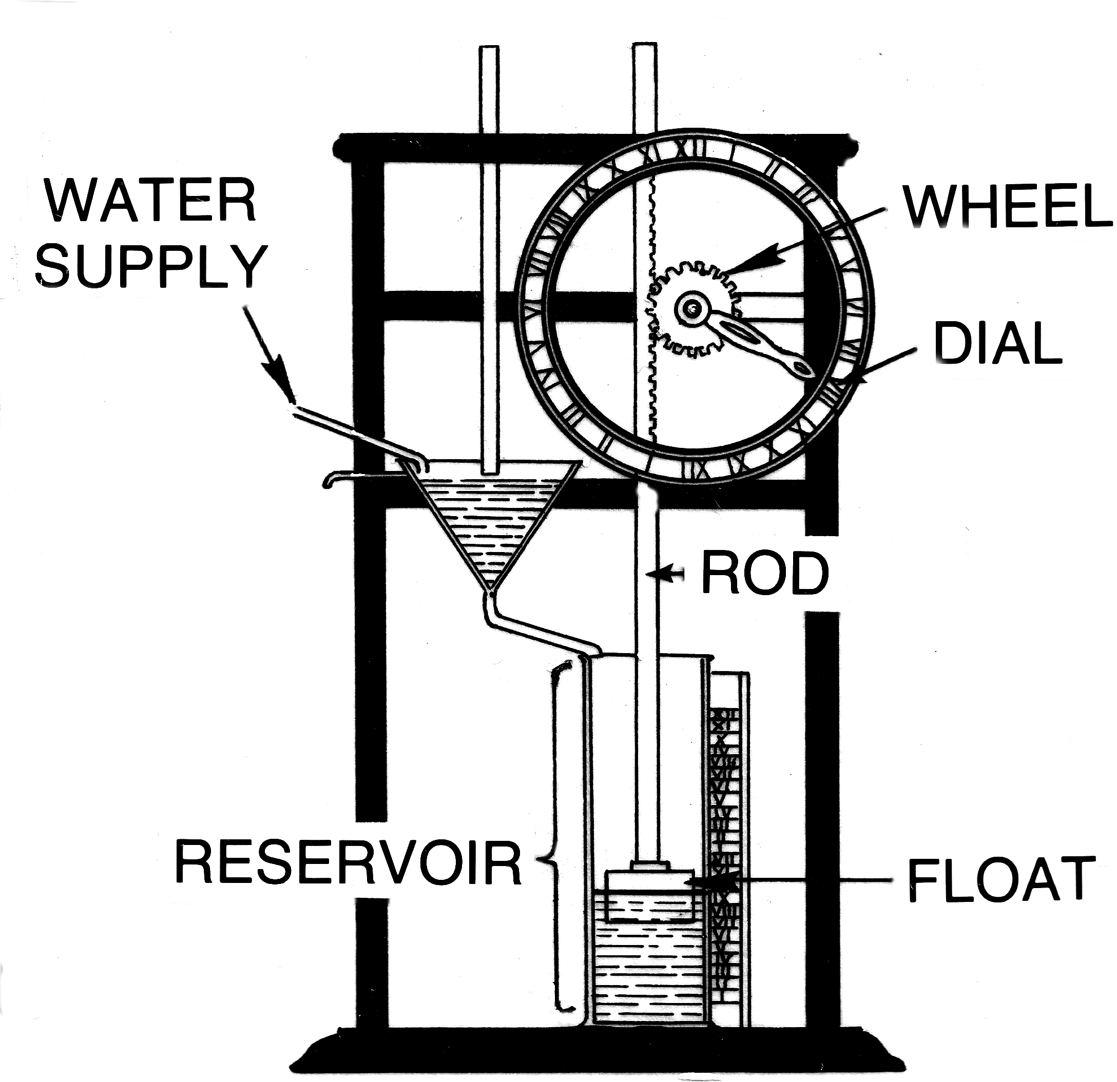
- Floating Indicators: Attach a float to a vertical rod that rises or falls with the water level. The rod passes through a guide with calibrated time markings, allowing you to read the time directly based on the float’s position.
- Mechanical Dials: Utilize gears driven by the water flow to move clock hands on a dial. This can be achieved by installing a small water wheel connected to a gear train, translating the water’s kinetic energy into rotational motion for the hands.
- Electronic Sensors: Integrate ultrasonic sensors or float switches connected to a microcontroller (like an Arduino). This setup can measure the water level and display the time digitally, combining ancient principles with modern technology.
Choose a method that suits your skills and desired aesthetic. If you prefer a traditional look, the floating indicator or mechanical dial may be more appropriate. For a blend of old and new, electronic sensors offer a modern twist on this ancient device.
By carefully designing the mechanism, calculating precise measurements, and selecting an appropriate time indication method, you’ll create a water clock that not only functions accurately but also serves as a fascinating conversation piece showcasing the intersection of history, science, and art.
